Camera Calibration and 3D Reconstruction
Overview
The functions in this section use a so-called pinhole camera model. More…
// enums

enum
{
    cv::@142::LMEDS  = 4,
    cv::@142::RANSAC = 8,
    cv::@142::RHO    = 16,
};

enum
{
    cv::@143::SOLVEPNP_ITERATIVE = 0,
    cv::@143::SOLVEPNP_EPNP      = 1,
    cv::@143::SOLVEPNP_P3P       = 2,
    cv::@143::SOLVEPNP_DLS       = 3,
    cv::@143::SOLVEPNP_UPNP      = 4,
    cv::@143::SOLVEPNP_AP3P      = 5,
};

enum
{
    cv::@144::CALIB_CB_ADAPTIVE_THRESH = 1,
    cv::@144::CALIB_CB_NORMALIZE_IMAGE = 2,
    cv::@144::CALIB_CB_FILTER_QUADS    = 4,
    cv::@144::CALIB_CB_FAST_CHECK      = 8,
};

enum
{
    cv::@145::CALIB_CB_SYMMETRIC_GRID  = 1,
    cv::@145::CALIB_CB_ASYMMETRIC_GRID = 2,
    cv::@145::CALIB_CB_CLUSTERING      = 4,
};

enum
{
    cv::@146::CALIB_USE_INTRINSIC_GUESS = 0x00001,
    cv::@146::CALIB_FIX_ASPECT_RATIO    = 0x00002,
    cv::@146::CALIB_FIX_PRINCIPAL_POINT = 0x00004,
    cv::@146::CALIB_ZERO_TANGENT_DIST   = 0x00008,
    cv::@146::CALIB_FIX_FOCAL_LENGTH    = 0x00010,
    cv::@146::CALIB_FIX_K1              = 0x00020,
    cv::@146::CALIB_FIX_K2              = 0x00040,
    cv::@146::CALIB_FIX_K3              = 0x00080,
    cv::@146::CALIB_FIX_K4              = 0x00800,
    cv::@146::CALIB_FIX_K5              = 0x01000,
    cv::@146::CALIB_FIX_K6              = 0x02000,
    cv::@146::CALIB_RATIONAL_MODEL      = 0x04000,
    cv::@146::CALIB_THIN_PRISM_MODEL    = 0x08000,
    cv::@146::CALIB_FIX_S1_S2_S3_S4     = 0x10000,
    cv::@146::CALIB_TILTED_MODEL        = 0x40000,
    cv::@146::CALIB_FIX_TAUX_TAUY       = 0x80000,
    cv::@146::CALIB_USE_QR              = 0x100000,
    cv::@146::CALIB_FIX_INTRINSIC       = 0x00100,
    cv::@146::CALIB_SAME_FOCAL_LENGTH   = 0x00200,
    cv::@146::CALIB_ZERO_DISPARITY      = 0x00400,
    cv::@146::CALIB_USE_LU              = (1 <<17),
};

enum
{
    cv::@147::FM_7POINT = 1,
    cv::@147::FM_8POINT = 2,
    cv::@147::FM_LMEDS  = 4,
    cv::@147::FM_RANSAC = 8,
};

// structs

struct cv::CirclesGridFinderParameters;

// classes

class cv::StereoBM;
class cv::StereoMatcher;
class cv::StereoSGBM;

// global functions

double
cv::calibrateCamera(
    InputArrayOfArrays objectPoints,
    InputArrayOfArrays imagePoints,
    Size imageSize,
    InputOutputArray cameraMatrix,
    InputOutputArray distCoeffs,
    OutputArrayOfArrays rvecs,
    OutputArrayOfArrays tvecs,
    OutputArray stdDeviationsIntrinsics,
    OutputArray stdDeviationsExtrinsics,
    OutputArray perViewErrors,
    int flags = 0,
    TermCriteria criteria = TermCriteria(TermCriteria::COUNT+TermCriteria::EPS, 30, DBL_EPSILON)
    );

double
cv::calibrateCamera(
    InputArrayOfArrays objectPoints,
    InputArrayOfArrays imagePoints,
    Size imageSize,
    InputOutputArray cameraMatrix,
    InputOutputArray distCoeffs,
    OutputArrayOfArrays rvecs,
    OutputArrayOfArrays tvecs,
    int flags = 0,
    TermCriteria criteria = TermCriteria(TermCriteria::COUNT+TermCriteria::EPS, 30, DBL_EPSILON)
    );

void
cv::calibrationMatrixValues(
    InputArray cameraMatrix,
    Size imageSize,
    double apertureWidth,
    double apertureHeight,
    double& fovx,
    double& fovy,
    double& focalLength,
    Point2d& principalPoint,
    double& aspectRatio
    );

void
cv::composeRT(
    InputArray rvec1,
    InputArray tvec1,
    InputArray rvec2,
    InputArray tvec2,
    OutputArray rvec3,
    OutputArray tvec3,
    OutputArray dr3dr1 = noArray(),
    OutputArray dr3dt1 = noArray(),
    OutputArray dr3dr2 = noArray(),
    OutputArray dr3dt2 = noArray(),
    OutputArray dt3dr1 = noArray(),
    OutputArray dt3dt1 = noArray(),
    OutputArray dt3dr2 = noArray(),
    OutputArray dt3dt2 = noArray()
    );

void
cv::computeCorrespondEpilines(
    InputArray points,
    int whichImage,
    InputArray F,
    OutputArray lines
    );

void
cv::convertPointsFromHomogeneous(
    InputArray src,
    OutputArray dst
    );

void
cv::convertPointsHomogeneous(
    InputArray src,
    OutputArray dst
    );

void
cv::convertPointsToHomogeneous(
    InputArray src,
    OutputArray dst
    );

void
cv::correctMatches(
    InputArray F,
    InputArray points1,
    InputArray points2,
    OutputArray newPoints1,
    OutputArray newPoints2
    );

void
cv::decomposeEssentialMat(
    InputArray E,
    OutputArray R1,
    OutputArray R2,
    OutputArray t
    );

int
cv::decomposeHomographyMat(
    InputArray H,
    InputArray K,
    OutputArrayOfArrays rotations,
    OutputArrayOfArrays translations,
    OutputArrayOfArrays normals
    );

void
cv::decomposeProjectionMatrix(
    InputArray projMatrix,
    OutputArray cameraMatrix,
    OutputArray rotMatrix,
    OutputArray transVect,
    OutputArray rotMatrixX = noArray(),
    OutputArray rotMatrixY = noArray(),
    OutputArray rotMatrixZ = noArray(),
    OutputArray eulerAngles = noArray()
    );

void
cv::drawChessboardCorners(
    InputOutputArray image,
    Size patternSize,
    InputArray corners,
    bool patternWasFound
    );

cv::Mat
cv::estimateAffine2D(
    InputArray from,
    InputArray to,
    OutputArray inliers = noArray(),
    int method = RANSAC,
    double ransacReprojThreshold = 3,
    size_t maxIters = 2000,
    double confidence = 0.99,
    size_t refineIters = 10
    );

int
cv::estimateAffine3D(
    InputArray src,
    InputArray dst,
    OutputArray out,
    OutputArray inliers,
    double ransacThreshold = 3,
    double confidence = 0.99
    );

cv::Mat
cv::estimateAffinePartial2D(
    InputArray from,
    InputArray to,
    OutputArray inliers = noArray(),
    int method = RANSAC,
    double ransacReprojThreshold = 3,
    size_t maxIters = 2000,
    double confidence = 0.99,
    size_t refineIters = 10
    );

void
cv::filterSpeckles(
    InputOutputArray img,
    double newVal,
    int maxSpeckleSize,
    double maxDiff,
    InputOutputArray buf = noArray()
    );

bool
cv::find4QuadCornerSubpix(
    InputArray img,
    InputOutputArray corners,
    Size region_size
    );

bool
cv::findChessboardCorners(
    InputArray image,
    Size patternSize,
    OutputArray corners,
    int flags = CALIB_CB_ADAPTIVE_THRESH+CALIB_CB_NORMALIZE_IMAGE
    );

bool
cv::findCirclesGrid(
    InputArray image,
    Size patternSize,
    OutputArray centers,
    int flags,
    const Ptr<FeatureDetector>& blobDetector,
    CirclesGridFinderParameters parameters
    );

bool
cv::findCirclesGrid(
    InputArray image,
    Size patternSize,
    OutputArray centers,
    int flags = CALIB_CB_SYMMETRIC_GRID,
    const Ptr<FeatureDetector>& blobDetector = SimpleBlobDetector::create()
    );

Mat
cv::findEssentialMat(
    InputArray points1,
    InputArray points2,
    InputArray cameraMatrix,
    int method = RANSAC,
    double prob = 0.999,
    double threshold = 1.0,
    OutputArray mask = noArray()
    );

Mat
cv::findEssentialMat(
    InputArray points1,
    InputArray points2,
    double focal = 1.0,
    Point2d pp = Point2d(0, 0),
    int method = RANSAC,
    double prob = 0.999,
    double threshold = 1.0,
    OutputArray mask = noArray()
    );

Mat
cv::findFundamentalMat(
    InputArray points1,
    InputArray points2,
    int method = FM_RANSAC,
    double param1 = 3.,
    double param2 = 0.99,
    OutputArray mask = noArray()
    );

Mat
cv::findFundamentalMat(
    InputArray points1,
    InputArray points2,
    OutputArray mask,
    int method = FM_RANSAC,
    double param1 = 3.,
    double param2 = 0.99
    );

Mat
cv::findHomography(
    InputArray srcPoints,
    InputArray dstPoints,
    int method = 0,
    double ransacReprojThreshold = 3,
    OutputArray mask = noArray(),
    const int maxIters = 2000,
    const double confidence = 0.995
    );

Mat
cv::findHomography(
    InputArray srcPoints,
    InputArray dstPoints,
    OutputArray mask,
    int method = 0,
    double ransacReprojThreshold = 3
    );

Mat
cv::getOptimalNewCameraMatrix(
    InputArray cameraMatrix,
    InputArray distCoeffs,
    Size imageSize,
    double alpha,
    Size newImgSize = Size(),
    Rect* validPixROI = 0,
    bool centerPrincipalPoint = false
    );

Rect
cv::getValidDisparityROI(
    Rect roi1,
    Rect roi2,
    int minDisparity,
    int numberOfDisparities,
    int SADWindowSize
    );

Mat
cv::initCameraMatrix2D(
    InputArrayOfArrays objectPoints,
    InputArrayOfArrays imagePoints,
    Size imageSize,
    double aspectRatio = 1.0
    );

void
cv::matMulDeriv(
    InputArray A,
    InputArray B,
    OutputArray dABdA,
    OutputArray dABdB
    );

void
cv::projectPoints(
    InputArray objectPoints,
    InputArray rvec,
    InputArray tvec,
    InputArray cameraMatrix,
    InputArray distCoeffs,
    OutputArray imagePoints,
    OutputArray jacobian = noArray(),
    double aspectRatio = 0
    );

int
cv::recoverPose(
    InputArray E,
    InputArray points1,
    InputArray points2,
    InputArray cameraMatrix,
    OutputArray R,
    OutputArray t,
    InputOutputArray mask = noArray()
    );

int
cv::recoverPose(
    InputArray E,
    InputArray points1,
    InputArray points2,
    OutputArray R,
    OutputArray t,
    double focal = 1.0,
    Point2d pp = Point2d(0, 0),
    InputOutputArray mask = noArray()
    );

int
cv::recoverPose(
    InputArray E,
    InputArray points1,
    InputArray points2,
    InputArray cameraMatrix,
    OutputArray R,
    OutputArray t,
    double distanceThresh,
    InputOutputArray mask = noArray(),
    OutputArray triangulatedPoints = noArray()
    );

float
cv::rectify3Collinear(
    InputArray cameraMatrix1,
    InputArray distCoeffs1,
    InputArray cameraMatrix2,
    InputArray distCoeffs2,
    InputArray cameraMatrix3,
    InputArray distCoeffs3,
    InputArrayOfArrays imgpt1,
    InputArrayOfArrays imgpt3,
    Size imageSize,
    InputArray R12,
    InputArray T12,
    InputArray R13,
    InputArray T13,
    OutputArray R1,
    OutputArray R2,
    OutputArray R3,
    OutputArray P1,
    OutputArray P2,
    OutputArray P3,
    OutputArray Q,
    double alpha,
    Size newImgSize,
    Rect* roi1,
    Rect* roi2,
    int flags
    );

void
cv::reprojectImageTo3D(
    InputArray disparity,
    OutputArray _3dImage,
    InputArray Q,
    bool handleMissingValues = false,
    int ddepth = -1
    );

void
cv::Rodrigues(
    InputArray src,
    OutputArray dst,
    OutputArray jacobian = noArray()
    );

Vec3d
cv::RQDecomp3x3(
    InputArray src,
    OutputArray mtxR,
    OutputArray mtxQ,
    OutputArray Qx = noArray(),
    OutputArray Qy = noArray(),
    OutputArray Qz = noArray()
    );

double
cv::sampsonDistance(
    InputArray pt1,
    InputArray pt2,
    InputArray F
    );

bool
cv::solvePnP(
    InputArray objectPoints,
    InputArray imagePoints,
    InputArray cameraMatrix,
    InputArray distCoeffs,
    OutputArray rvec,
    OutputArray tvec,
    bool useExtrinsicGuess = false,
    int flags = SOLVEPNP_ITERATIVE
    );

bool
cv::solvePnPRansac(
    InputArray objectPoints,
    InputArray imagePoints,
    InputArray cameraMatrix,
    InputArray distCoeffs,
    OutputArray rvec,
    OutputArray tvec,
    bool useExtrinsicGuess = false,
    int iterationsCount = 100,
    float reprojectionError = 8.0,
    double confidence = 0.99,
    OutputArray inliers = noArray(),
    int flags = SOLVEPNP_ITERATIVE
    );

double
cv::stereoCalibrate(
    InputArrayOfArrays objectPoints,
    InputArrayOfArrays imagePoints1,
    InputArrayOfArrays imagePoints2,
    InputOutputArray cameraMatrix1,
    InputOutputArray distCoeffs1,
    InputOutputArray cameraMatrix2,
    InputOutputArray distCoeffs2,
    Size imageSize,
    OutputArray R,
    OutputArray T,
    OutputArray E,
    OutputArray F,
    int flags = CALIB_FIX_INTRINSIC,
    TermCriteria criteria = TermCriteria(TermCriteria::COUNT+TermCriteria::EPS, 30, 1e-6)
    );

void
cv::stereoRectify(
    InputArray cameraMatrix1,
    InputArray distCoeffs1,
    InputArray cameraMatrix2,
    InputArray distCoeffs2,
    Size imageSize,
    InputArray R,
    InputArray T,
    OutputArray R1,
    OutputArray R2,
    OutputArray P1,
    OutputArray P2,
    OutputArray Q,
    int flags = CALIB_ZERO_DISPARITY,
    double alpha = -1,
    Size newImageSize = Size(),
    Rect* validPixROI1 = 0,
    Rect* validPixROI2 = 0
    );

bool
cv::stereoRectifyUncalibrated(
    InputArray points1,
    InputArray points2,
    InputArray F,
    Size imgSize,
    OutputArray H1,
    OutputArray H2,
    double threshold = 5
    );

void
cv::triangulatePoints(
    InputArray projMatr1,
    InputArray projMatr2,
    InputArray projPoints1,
    InputArray projPoints2,
    OutputArray points4D
    );

void
cv::validateDisparity(
    InputOutputArray disparity,
    InputArray cost,
    int minDisparity,
    int numberOfDisparities,
    int disp12MaxDisp = 1
    );
Detailed Documentation
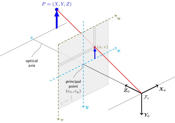
The functions in this section use a so-called pinhole camera model. In this model, a scene view is formed by projecting 3D points into the image plane using a perspective transformation.
or
where:
- \((X, Y, Z)\) are the coordinates of a 3D point in the world coordinate space
- \((u, v)\) are the coordinates of the projection point in pixels
- \(A\) is a camera matrix, or a matrix of intrinsic parameters
- \((cx, cy)\) is a principal point that is usually at the image center
- \(fx, fy\) are the focal lengths expressed in pixel units.
Thus, if an image from the camera is scaled by a factor, all of these parameters should be scaled (multiplied/divided, respectively) by the same factor. The matrix of intrinsic parameters does not depend on the scene viewed. So, once estimated, it can be re-used as long as the focal length is fixed (in case of zoom lens). The joint rotation-translation matrix \([R|t]\) is called a matrix of extrinsic parameters. It is used to describe the camera motion around a static scene, or vice versa, rigid motion of an object in front of a still camera. That is, \([R|t]\) translates coordinates of a point \((X, Y, Z)\) to a coordinate system, fixed with respect to the camera. The transformation above is equivalent to the following (when \(z \ne 0\)):
The following figure illustrates the pinhole camera model.
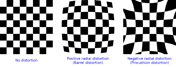
Real lenses usually have some distortion, mostly radial distortion and slight tangential distortion. So, the above model is extended as:
\(k_1\), \(k_2\), \(k_3\), \(k_4\), \(k_5\), and \(k_6\) are radial distortion coefficients. \(p_1\) and \(p_2\) are tangential distortion coefficients. \(s_1\), \(s_2\), \(s_3\), and \(s_4\), are the thin prism distortion coefficients. Higher-order coefficients are not considered in OpenCV.
The next figure shows two common types of radial distortion: barrel distortion (typically \(k_1 > 0\) and pincushion distortion (typically \(k_1 < 0\)).
In some cases the image sensor may be tilted in order to focus an oblique plane in front of the camera (Scheimpfug condition). This can be useful for particle image velocimetry (PIV) or triangulation with a laser fan. The tilt causes a perspective distortion of \(x''\) and \(y''\). This distortion can be modelled in the following way, see e.g. [50].
where the matrix \(R(\tau_x, \tau_y)\) is defined by two rotations with angular parameter \(\tau_x\) and \(\tau_y\), respectively,
In the functions below the coefficients are passed or returned as
vector. That is, if the vector contains four elements, it means that \(k_3=0\). The distortion coefficients do not depend on the scene viewed. Thus, they also belong to the intrinsic camera parameters. And they remain the same regardless of the captured image resolution. If, for example, a camera has been calibrated on images of 320 x 240 resolution, absolutely the same distortion coefficients can be used for 640 x 480 images from the same camera while \(f_x\), \(f_y\), \(c_x\), and \(c_y\) need to be scaled appropriately.
The functions below use the above model to do the following:
- Project 3D points to the image plane given intrinsic and extrinsic parameters.
- Compute extrinsic parameters given intrinsic parameters, a few 3D points, and their projections.
- Estimate intrinsic and extrinsic camera parameters from several views of a known calibration pattern (every view is described by several 3D-2D point correspondences).
- Estimate the relative position and orientation of the stereo camera “heads” and compute the rectification* transformation that makes the camera optical axes parallel.
- A calibration sample for 3 cameras in horizontal position can be found at opencv_source_code/samples/cpp/3calibration.cpp
- A calibration sample based on a sequence of images can be found at opencv_source_code/samples/cpp/calibration.cpp
- A calibration sample in order to do 3D reconstruction can be found at opencv_source_code/samples/cpp/build3dmodel.cpp
- A calibration sample of an artificially generated camera and chessboard patterns can be found at opencv_source_code/samples/cpp/calibration_artificial.cpp
- A calibration example on stereo calibration can be found at opencv_source_code/samples/cpp/stereo_calib.cpp
- A calibration example on stereo matching can be found at opencv_source_code/samples/cpp/stereo_match.cpp
- (Python) A camera calibration sample can be found at opencv_source_code/samples/python/calibrate.py
Enum Values
LMEDS
least-median algorithm
RANSAC
RANSAC algorithm.
RHO
RHO algorithm.
SOLVEPNP_EPNP
EPnP: Efficient Perspective-n-Point Camera Pose Estimation [45].
SOLVEPNP_P3P
Complete Solution Classification for the Perspective-Three-Point Problem [30].
SOLVEPNP_DLS
A Direct Least-Squares (DLS) Method for PnP [38].
SOLVEPNP_UPNP
Exhaustive Linearization for Robust Camera Pose and Focal Length Estimation [65].
SOLVEPNP_AP3P
An Efficient Algebraic Solution to the Perspective-Three-Point Problem [42].
CALIB_USE_QR
use QR instead of SVD decomposition for solving. Faster but potentially less precise
CALIB_USE_LU
use LU instead of SVD decomposition for solving. much faster but potentially less precise
FM_7POINT
7-point algorithm
FM_8POINT
8-point algorithm
FM_LMEDS
least-median algorithm
FM_RANSAC
RANSAC algorithm.
Global Functions
double
cv::calibrateCamera(
    InputArrayOfArrays objectPoints,
    InputArrayOfArrays imagePoints,
    Size imageSize,
    InputOutputArray cameraMatrix,
    InputOutputArray distCoeffs,
    OutputArrayOfArrays rvecs,
    OutputArrayOfArrays tvecs,
    OutputArray stdDeviationsIntrinsics,
    OutputArray stdDeviationsExtrinsics,
    OutputArray perViewErrors,
    int flags = 0,
    TermCriteria criteria = TermCriteria(TermCriteria::COUNT+TermCriteria::EPS, 30, DBL_EPSILON)
    )
Finds the camera intrinsic and extrinsic parameters from several views of a calibration pattern.
The function estimates the intrinsic camera parameters and extrinsic parameters for each of the views. The algorithm is based on [96] and [8]. The coordinates of 3D object points and their corresponding 2D projections in each view must be specified. That may be achieved by using an object with a known geometry and easily detectable feature points. Such an object is called a calibration rig or calibration pattern, and OpenCV has built-in support for a chessboard as a calibration rig (see findChessboardCorners ). Currently, initialization of intrinsic parameters (when CALIB_USE_INTRINSIC_GUESS is not set) is only implemented for planar calibration patterns (where Z-coordinates of the object points must be all zeros). 3D calibration rigs can also be used as long as initial cameraMatrix is provided.
The algorithm performs the following steps:
- Compute the initial intrinsic parameters (the option only available for planar calibration patterns) or read them from the input parameters. The distortion coefficients are all set to zeros initially unless some of CALIB_FIX_K? are specified.
- Estimate the initial camera pose as if the intrinsic parameters have been already known. This is done using solvePnP .
- Run the global Levenberg-Marquardt optimization algorithm to minimize the reprojection error, that is, the total sum of squared distances between the observed feature points imagePoints and the projected (using the current estimates for camera parameters and the poses) object points objectPoints. See projectPoints for details.
If you use a non-square (=non-NxN) grid and findChessboardCorners for calibration, and calibrateCamera returns bad values (zero distortion coefficients, an image center very far from (w/2-0.5,h/2-0.5), and/or large differences between \(f_x\) and \(f_y\) (ratios of 10:1 or more)), then you have probably used patternSize=cvSize(rows,cols) instead of using patternSize=cvSize(cols,rows) in findChessboardCorners .
Parameters:
| objectPoints | In the new interface it is a vector of vectors of calibration pattern points in the calibration pattern coordinate space (e.g. std::vector<std::vector<cv::Vec3f>>). The outer vector contains as many elements as the number of the pattern views. If the same calibration pattern is shown in each view and it is fully visible, all the vectors will be the same. Although, it is possible to use partially occluded patterns, or even different patterns in different views. Then, the vectors will be different. The points are 3D, but since they are in a pattern coordinate system, then, if the rig is planar, it may make sense to put the model to a XY coordinate plane so that Z-coordinate of each input object point is 0. In the old interface all the vectors of object points from different views are concatenated together. |
| imagePoints | In the new interface it is a vector of vectors of the projections of calibration pattern points (e.g. std::vector<std::vector<cv::Vec2f>>). imagePoints.size() and objectPoints.size() and imagePoints[i].size() must be equal to objectPoints[i].size() for each i. In the old interface all the vectors of object points from different views are concatenated together. |
| imageSize | Size of the image used only to initialize the intrinsic camera matrix. |
| cameraMatrix | Output 3x3 floating-point camera matrix \(A = \vecthreethree{f_x}{0}{c_x}{0}{f_y}{c_y}{0}{0}{1}\). If CV_CALIB_USE_INTRINSIC_GUESS and/or CALIB_FIX_ASPECT_RATIO are specified, some or all of fx, fy, cx, cy must be initialized before calling the function. |
| distCoeffs | Output vector of distortion coefficients \((k_1, k_2, p_1, p_2[, k_3[, k_4, k_5, k_6 [, s_1, s_2, s_3, s_4[, \tau_x, \tau_y]]]])\) of 4, 5, 8, 12 or 14 elements. |
| rvecs | Output vector of rotation vectors (see Rodrigues ) estimated for each pattern view (e.g. std::vector<cv::Mat>>). That is, each k-th rotation vector together with the corresponding k-th translation vector (see the next output parameter description) brings the calibration pattern from the model coordinate space (in which object points are specified) to the world coordinate space, that is, a real position of the calibration pattern in the k-th pattern view (k=0.. M -1). |
| tvecs | Output vector of translation vectors estimated for each pattern view. |
| stdDeviationsIntrinsics | Output vector of standard deviations estimated for intrinsic parameters. Order of deviations values: \((f_x, f_y, c_x, c_y, k_1, k_2, p_1, p_2, k_3, k_4, k_5, k_6 , s_1, s_2, s_3, s_4, \tau_x, \tau_y)\) If one of parameters is not estimated, it’s deviation is equals to zero. |
| stdDeviationsExtrinsics | Output vector of standard deviations estimated for extrinsic parameters. Order of deviations values: \((R_1, T_1, \dotsc , R_M, T_M)\) where M is number of pattern views, \(R_i, T_i\) are concatenated 1x3 vectors. |
| perViewErrors | Output vector of the RMS re-projection error estimated for each pattern view. |
| flags | Different flags that may be zero or a combination of the following values:
|
| criteria | Termination criteria for the iterative optimization algorithm. |
Returns:
the overall RMS re-projection error.
See also:
findChessboardCorners, solvePnP, initCameraMatrix2D, stereoCalibrate, undistort
void
cv::calibrationMatrixValues(
    InputArray cameraMatrix,
    Size imageSize,
    double apertureWidth,
    double apertureHeight,
    double& fovx,
    double& fovy,
    double& focalLength,
    Point2d& principalPoint,
    double& aspectRatio
    )
Computes useful camera characteristics from the camera matrix.
The function computes various useful camera characteristics from the previously estimated camera matrix.
Do keep in mind that the unity measure ‘mm’ stands for whatever unit of measure one chooses for the chessboard pitch (it can thus be any value).
Parameters:
| cameraMatrix | Input camera matrix that can be estimated by calibrateCamera or stereoCalibrate . |
| imageSize | Input image size in pixels. |
| apertureWidth | Physical width in mm of the sensor. |
| apertureHeight | Physical height in mm of the sensor. |
| fovx | Output field of view in degrees along the horizontal sensor axis. |
| fovy | Output field of view in degrees along the vertical sensor axis. |
| focalLength | Focal length of the lens in mm. |
| principalPoint | Principal point in mm. |
| aspectRatio | \(f_y/f_x\) |
void
cv::composeRT(
    InputArray rvec1,
    InputArray tvec1,
    InputArray rvec2,
    InputArray tvec2,
    OutputArray rvec3,
    OutputArray tvec3,
    OutputArray dr3dr1 = noArray(),
    OutputArray dr3dt1 = noArray(),
    OutputArray dr3dr2 = noArray(),
    OutputArray dr3dt2 = noArray(),
    OutputArray dt3dr1 = noArray(),
    OutputArray dt3dt1 = noArray(),
    OutputArray dt3dr2 = noArray(),
    OutputArray dt3dt2 = noArray()
    )
Combines two rotation-and-shift transformations.
The functions compute:
where \(\mathrm{rodrigues}\) denotes a rotation vector to a rotation matrix transformation, and \(\mathrm{rodrigues}^{-1}\) denotes the inverse transformation. See Rodrigues for details.
Also, the functions can compute the derivatives of the output vectors with regards to the input vectors (see matMulDeriv ). The functions are used inside stereoCalibrate but can also be used in your own code where Levenberg-Marquardt or another gradient-based solver is used to optimize a function that contains a matrix multiplication.
Parameters:
| rvec1 | First rotation vector. |
| tvec1 | First translation vector. |
| rvec2 | Second rotation vector. |
| tvec2 | Second translation vector. |
| rvec3 | Output rotation vector of the superposition. |
| tvec3 | Output translation vector of the superposition. |
| dr3dr1 | |
| dr3dt1 | |
| dr3dr2 | |
| dr3dt2 | |
| dt3dr1 | |
| dt3dt1 | |
| dt3dr2 | |
| dt3dt2 | Optional output derivatives of rvec3 or tvec3 with regard to rvec1, rvec2, tvec1 and tvec2, respectively. |
void
cv::computeCorrespondEpilines(
    InputArray points,
    int whichImage,
    InputArray F,
    OutputArray lines
    )
For points in an image of a stereo pair, computes the corresponding epilines in the other image.
For every point in one of the two images of a stereo pair, the function finds the equation of the corresponding epipolar line in the other image.
From the fundamental matrix definition (see findFundamentalMat ), line \(l^{(2)}_i\) in the second image for the point \(p^{(1)}_i\) in the first image (when whichImage=1 ) is computed as:
And vice versa, when whichImage=2, \(l^{(1)}_i\) is computed from \(p^{(2)}_i\) as:
Line coefficients are defined up to a scale. They are normalized so that \(a_i^2+b_i^2=1\).
Parameters:
| points | Input points. \(N \times 1\) or \(1 \times N\) matrix of type CV_32FC2 or vector<Point2f> . |
| whichImage | Index of the image (1 or 2) that contains the points . |
| F | Fundamental matrix that can be estimated using findFundamentalMat or stereoRectify . |
| lines | Output vector of the epipolar lines corresponding to the points in the other image. Each line \(ax + by + c=0\) is encoded by 3 numbers \((a, b, c)\). |
void
cv::convertPointsFromHomogeneous(
    InputArray src,
    OutputArray dst
    )
Converts points from homogeneous to Euclidean space.
The function converts points homogeneous to Euclidean space using perspective projection. That is, each point (x1, x2, … x(n-1), xn) is converted to (x1/xn, x2/xn, …, x(n-1)/xn). When xn=0, the output point coordinates will be (0,0,0,…).
Parameters:
| src | Input vector of N-dimensional points. |
| dst | Output vector of N-1-dimensional points. |
void
cv::convertPointsHomogeneous(
    InputArray src,
    OutputArray dst
    )
Converts points to/from homogeneous coordinates.
The function converts 2D or 3D points from/to homogeneous coordinates by calling either convertPointsToHomogeneous or convertPointsFromHomogeneous.
The function is obsolete. Use one of the previous two functions instead.
Parameters:
| src | Input array or vector of 2D, 3D, or 4D points. |
| dst | Output vector of 2D, 3D, or 4D points. |
void
cv::convertPointsToHomogeneous(
    InputArray src,
    OutputArray dst
    )
Converts points from Euclidean to homogeneous space.
The function converts points from Euclidean to homogeneous space by appending 1’s to the tuple of point coordinates. That is, each point (x1, x2, …, xn) is converted to (x1, x2, …, xn, 1).
Parameters:
| src | Input vector of N-dimensional points. |
| dst | Output vector of N+1-dimensional points. |
void
cv::correctMatches(
    InputArray F,
    InputArray points1,
    InputArray points2,
    OutputArray newPoints1,
    OutputArray newPoints2
    )
Refines coordinates of corresponding points.
The function implements the Optimal Triangulation Method (see Multiple View Geometry for details). For each given point correspondence points1[i] <-> points2[i], and a fundamental matrix F, it computes the corrected correspondences newPoints1[i] <-> newPoints2[i] that minimize the geometric error \(d(points1[i], newPoints1[i])^2 + d(points2[i],newPoints2[i])^2\) (where \(d(a,b)\) is the geometric distance between points \(a\) and \(b\)) subject to the epipolar constraint \(newPoints2^T * F * newPoints1 = 0\).
Parameters:
| F | 3x3 fundamental matrix. |
| points1 | 1xN array containing the first set of points. |
| points2 | 1xN array containing the second set of points. |
| newPoints1 | The optimized points1. |
| newPoints2 | The optimized points2. |
void
cv::decomposeEssentialMat(
    InputArray E,
    OutputArray R1,
    OutputArray R2,
    OutputArray t
    )
Decompose an essential matrix to possible rotations and translation.
This function decompose an essential matrix E using svd decomposition [36]. Generally 4 possible poses exists for a given E. They are \([R_1, t]\), \([R_1, -t]\), \([R_2, t]\), \([R_2, -t]\). By decomposing E, you can only get the direction of the translation, so the function returns unit t.
Parameters:
| E | The input essential matrix. |
| R1 | One possible rotation matrix. |
| R2 | Another possible rotation matrix. |
| t | One possible translation. |
int
cv::decomposeHomographyMat(
    InputArray H,
    InputArray K,
    OutputArrayOfArrays rotations,
    OutputArrayOfArrays translations,
    OutputArrayOfArrays normals
    )
Decompose a homography matrix to rotation(s), translation(s) and plane normal(s).
This function extracts relative camera motion between two views observing a planar object from the homography H induced by the plane. The intrinsic camera matrix K must also be provided. The function may return up to four mathematical solution sets. At least two of the solutions may further be invalidated if point correspondences are available by applying positive depth constraint (all points must be in front of the camera). The decomposition method is described in detail in [53].
Parameters:
| H | The input homography matrix between two images. |
| K | The input intrinsic camera calibration matrix. |
| rotations | Array of rotation matrices. |
| translations | Array of translation matrices. |
| normals | Array of plane normal matrices. |
void
cv::decomposeProjectionMatrix(
    InputArray projMatrix,
    OutputArray cameraMatrix,
    OutputArray rotMatrix,
    OutputArray transVect,
    OutputArray rotMatrixX = noArray(),
    OutputArray rotMatrixY = noArray(),
    OutputArray rotMatrixZ = noArray(),
    OutputArray eulerAngles = noArray()
    )
Decomposes a projection matrix into a rotation matrix and a camera matrix.
The function computes a decomposition of a projection matrix into a calibration and a rotation matrix and the position of a camera.
It optionally returns three rotation matrices, one for each axis, and three Euler angles that could be used in OpenGL. Note, there is always more than one sequence of rotations about the three principal axes that results in the same orientation of an object, eg. see [78]. Returned tree rotation matrices and corresponding three Euler angules are only one of the possible solutions.
The function is based on RQDecomp3x3 .
Parameters:
| projMatrix | 3x4 input projection matrix P. |
| cameraMatrix | Output 3x3 camera matrix K. |
| rotMatrix | Output 3x3 external rotation matrix R. |
| transVect | Output 4x1 translation vector T. |
| rotMatrixX | Optional 3x3 rotation matrix around x-axis. |
| rotMatrixY | Optional 3x3 rotation matrix around y-axis. |
| rotMatrixZ | Optional 3x3 rotation matrix around z-axis. |
| eulerAngles | Optional three-element vector containing three Euler angles of rotation in degrees. |
void
cv::drawChessboardCorners(
    InputOutputArray image,
    Size patternSize,
    InputArray corners,
    bool patternWasFound
    )
Renders the detected chessboard corners.
The function draws individual chessboard corners detected either as red circles if the board was not found, or as colored corners connected with lines if the board was found.
Parameters:
| image | Destination image. It must be an 8-bit color image. |
| patternSize | Number of inner corners per a chessboard row and column (patternSize = cv::Size(points_per_row,points_per_column)). |
| corners | Array of detected corners, the output of findChessboardCorners. |
| patternWasFound | Parameter indicating whether the complete board was found or not. The return value of findChessboardCorners should be passed here. |
cv::Mat
cv::estimateAffine2D(
    InputArray from,
    InputArray to,
    OutputArray inliers = noArray(),
    int method = RANSAC,
    double ransacReprojThreshold = 3,
    size_t maxIters = 2000,
    double confidence = 0.99,
    size_t refineIters = 10
    )
Computes an optimal affine transformation between two 2D point sets.
The function estimates an optimal 2D affine transformation between two 2D point sets using the selected robust algorithm.
The computed transformation is then refined further (using only inliers) with the Levenberg-Marquardt method to reduce the re-projection error even more.
The RANSAC method can handle practically any ratio of outliers but need a threshold to distinguish inliers from outliers. The method LMeDS does not need any threshold but it works correctly only when there are more than 50% of inliers.
Parameters:
| from | First input 2D point set. |
| to | Second input 2D point set. |
| inliers | Output vector indicating which points are inliers. |
| method | Robust method used to compute tranformation. The following methods are possible:
|
| ransacReprojThreshold | Maximum reprojection error in the RANSAC algorithm to consider a point as an inlier. Applies only to RANSAC. |
| maxIters | The maximum number of robust method iterations, 2000 is the maximum it can be. |
| confidence | Confidence level, between 0 and 1, for the estimated transformation. Anything between 0.95 and 0.99 is usually good enough. Values too close to 1 can slow down the estimation significantly. Values lower than 0.8-0.9 can result in an incorrectly estimated transformation. |
| refineIters | Maximum number of iterations of refining algorithm (Levenberg-Marquardt). Passing 0 will disable refining, so the output matrix will be output of robust method. |
Returns:
Output 2D affine transformation matrix \(2 \times 3\) or empty matrix if transformation could not be estimated.
See also:
estimateAffinePartial2D, getAffineTransform
int
cv::estimateAffine3D(
    InputArray src,
    InputArray dst,
    OutputArray out,
    OutputArray inliers,
    double ransacThreshold = 3,
    double confidence = 0.99
    )
Computes an optimal affine transformation between two 3D point sets.
The function estimates an optimal 3D affine transformation between two 3D point sets using the RANSAC algorithm.
Parameters:
| src | First input 3D point set. |
| dst | Second input 3D point set. |
| out | Output 3D affine transformation matrix \(3 \times 4\). |
| inliers | Output vector indicating which points are inliers. |
| ransacThreshold | Maximum reprojection error in the RANSAC algorithm to consider a point as an inlier. |
| confidence | Confidence level, between 0 and 1, for the estimated transformation. Anything between 0.95 and 0.99 is usually good enough. Values too close to 1 can slow down the estimation significantly. Values lower than 0.8-0.9 can result in an incorrectly estimated transformation. |
cv::Mat
cv::estimateAffinePartial2D(
    InputArray from,
    InputArray to,
    OutputArray inliers = noArray(),
    int method = RANSAC,
    double ransacReprojThreshold = 3,
    size_t maxIters = 2000,
    double confidence = 0.99,
    size_t refineIters = 10
    )
Computes an optimal limited affine transformation with 4 degrees of freedom between two 2D point sets.
The function estimates an optimal 2D affine transformation with 4 degrees of freedom limited to combinations of translation, rotation, and uniform scaling. Uses the selected algorithm for robust estimation.
The computed transformation is then refined further (using only inliers) with the Levenberg-Marquardt method to reduce the re-projection error even more.
Estimated transformation matrix is:
Where \(\theta\) is the rotation angle, \(s\) the scaling factor and \(tx, ty\) are translations in \(x, y\) axes respectively.
The RANSAC method can handle practically any ratio of outliers but need a threshold to distinguish inliers from outliers. The method LMeDS does not need any threshold but it works correctly only when there are more than 50% of inliers.
Parameters:
| from | First input 2D point set. |
| to | Second input 2D point set. |
| inliers | Output vector indicating which points are inliers. |
| method | Robust method used to compute tranformation. The following methods are possible:
|
| ransacReprojThreshold | Maximum reprojection error in the RANSAC algorithm to consider a point as an inlier. Applies only to RANSAC. |
| maxIters | The maximum number of robust method iterations, 2000 is the maximum it can be. |
| confidence | Confidence level, between 0 and 1, for the estimated transformation. Anything between 0.95 and 0.99 is usually good enough. Values too close to 1 can slow down the estimation significantly. Values lower than 0.8-0.9 can result in an incorrectly estimated transformation. |
| refineIters | Maximum number of iterations of refining algorithm (Levenberg-Marquardt). Passing 0 will disable refining, so the output matrix will be output of robust method. |
Returns:
Output 2D affine transformation (4 degrees of freedom) matrix \(2 \times 3\) or empty matrix if transformation could not be estimated.
See also:
estimateAffine2D, getAffineTransform
void
cv::filterSpeckles(
    InputOutputArray img,
    double newVal,
    int maxSpeckleSize,
    double maxDiff,
    InputOutputArray buf = noArray()
    )
Filters off small noise blobs (speckles) in the disparity map.
Parameters:
| img | The input 16-bit signed disparity image |
| newVal | The disparity value used to paint-off the speckles |
| maxSpeckleSize | The maximum speckle size to consider it a speckle. Larger blobs are not affected by the algorithm |
| maxDiff | Maximum difference between neighbor disparity pixels to put them into the same blob. Note that since StereoBM, StereoSGBM and may be other algorithms return a fixed-point disparity map, where disparity values are multiplied by 16, this scale factor should be taken into account when specifying this parameter value. |
| buf | The optional temporary buffer to avoid memory allocation within the function. |
bool
cv::find4QuadCornerSubpix(
    InputArray img,
    InputOutputArray corners,
    Size region_size
    )
finds subpixel-accurate positions of the chessboard corners
bool
cv::findChessboardCorners(
    InputArray image,
    Size patternSize,
    OutputArray corners,
    int flags = CALIB_CB_ADAPTIVE_THRESH+CALIB_CB_NORMALIZE_IMAGE
    )
Finds the positions of internal corners of the chessboard.
The function attempts to determine whether the input image is a view of the chessboard pattern and locate the internal chessboard corners. The function returns a non-zero value if all of the corners are found and they are placed in a certain order (row by row, left to right in every row). Otherwise, if the function fails to find all the corners or reorder them, it returns 0. For example, a regular chessboard has 8 x 8 squares and 7 x 7 internal corners, that is, points where the black squares touch each other. The detected coordinates are approximate, and to determine their positions more accurately, the function calls cornerSubPix. You also may use the function cornerSubPix with different parameters if returned coordinates are not accurate enough.
Sample usage of detecting and drawing chessboard corners: :
Size patternsize(8,6); //interior number of corners
Mat gray = ....; //source image
vector<Point2f> corners; //this will be filled by the detected corners

//CALIB_CB_FAST_CHECK saves a lot of time on images
//that do not contain any chessboard corners
bool patternfound = findChessboardCorners(gray, patternsize, corners,
        CALIB_CB_ADAPTIVE_THRESH + CALIB_CB_NORMALIZE_IMAGE
        + CALIB_CB_FAST_CHECK);

if(patternfound)
  cornerSubPix(gray, corners, Size(11, 11), Size(-1, -1),
    TermCriteria(CV_TERMCRIT_EPS + CV_TERMCRIT_ITER, 30, 0.1));

drawChessboardCorners(img, patternsize, Mat(corners), patternfound);
The function requires white space (like a square-thick border, the wider the better) around the board to make the detection more robust in various environments. Otherwise, if there is no border and the background is dark, the outer black squares cannot be segmented properly and so the square grouping and ordering algorithm fails.
Parameters:
| image | Source chessboard view. It must be an 8-bit grayscale or color image. |
| patternSize | Number of inner corners per a chessboard row and column ( patternSize = cvSize(points_per_row,points_per_colum) = cvSize(columns,rows) ). |
| corners | Output array of detected corners. |
| flags | Various operation flags that can be zero or a combination of the following values:
|
bool
cv::findCirclesGrid(
    InputArray image,
    Size patternSize,
    OutputArray centers,
    int flags,
    const Ptr<FeatureDetector>& blobDetector,
    CirclesGridFinderParameters parameters
    )
Finds centers in the grid of circles.
The function attempts to determine whether the input image contains a grid of circles. If it is, the function locates centers of the circles. The function returns a non-zero value if all of the centers have been found and they have been placed in a certain order (row by row, left to right in every row). Otherwise, if the function fails to find all the corners or reorder them, it returns 0.
Sample usage of detecting and drawing the centers of circles: :
Size patternsize(7,7); //number of centers
Mat gray = ....; //source image
vector<Point2f> centers; //this will be filled by the detected centers

bool patternfound = findCirclesGrid(gray, patternsize, centers);

drawChessboardCorners(img, patternsize, Mat(centers), patternfound);
The function requires white space (like a square-thick border, the wider the better) around the board to make the detection more robust in various environments.
Parameters:
| image | grid view of input circles; it must be an 8-bit grayscale or color image. |
| patternSize | number of circles per row and column ( patternSize = Size(points_per_row, points_per_colum) ). |
| centers | output array of detected centers. |
| flags | various operation flags that can be one of the following values:
|
| blobDetector | feature detector that finds blobs like dark circles on light background. |
| parameters | struct for finding circles in a grid pattern. |
bool
cv::findCirclesGrid(
    InputArray image,
    Size patternSize,
    OutputArray centers,
    int flags = CALIB_CB_SYMMETRIC_GRID,
    const Ptr<FeatureDetector>& blobDetector = SimpleBlobDetector::create()
    )
This is an overloaded member function, provided for convenience. It differs from the above function only in what argument(s) it accepts.
Mat
cv::findEssentialMat(
    InputArray points1,
    InputArray points2,
    InputArray cameraMatrix,
    int method = RANSAC,
    double prob = 0.999,
    double threshold = 1.0,
    OutputArray mask = noArray()
    )
Calculates an essential matrix from the corresponding points in two images.
This function estimates essential matrix based on the five-point algorithm solver in [63]. [79] is also a related. The epipolar geometry is described by the following equation:
where \(E\) is an essential matrix, \(p_1\) and \(p_2\) are corresponding points in the first and the second images, respectively. The result of this function may be passed further to decomposeEssentialMat or recoverPose to recover the relative pose between cameras.
Parameters:
| points1 | Array of N (N >= 5) 2D points from the first image. The point coordinates should be floating-point (single or double precision). |
| points2 | Array of the second image points of the same size and format as points1 . |
| cameraMatrix | Camera matrix \(K = \vecthreethree{f_x}{0}{c_x}{0}{f_y}{c_y}{0}{0}{1}\). Note that this function assumes that points1 and points2 are feature points from cameras with the same camera matrix. |
| method | Method for computing a fundamental matrix.
|
| prob | Parameter used for the RANSAC or LMedS methods only. It specifies a desirable level of confidence (probability) that the estimated matrix is correct. |
| threshold | Parameter used for RANSAC. It is the maximum distance from a point to an epipolar line in pixels, beyond which the point is considered an outlier and is not used for computing the final fundamental matrix. It can be set to something like 1-3, depending on the accuracy of the point localization, image resolution, and the image noise. |
| mask | Output array of N elements, every element of which is set to 0 for outliers and to 1 for the other points. The array is computed only in the RANSAC and LMedS methods. |
Mat
cv::findEssentialMat(
    InputArray points1,
    InputArray points2,
    double focal = 1.0,
    Point2d pp = Point2d(0, 0),
    int method = RANSAC,
    double prob = 0.999,
    double threshold = 1.0,
    OutputArray mask = noArray()
    )
This is an overloaded member function, provided for convenience. It differs from the above function only in what argument(s) it accepts. This function differs from the one above that it computes camera matrix from focal length and principal point:
Parameters:
| points1 | Array of N (N >= 5) 2D points from the first image. The point coordinates should be floating-point (single or double precision). |
| points2 | Array of the second image points of the same size and format as points1 . |
| focal | focal length of the camera. Note that this function assumes that points1 and points2 are feature points from cameras with same focal length and principal point. |
| pp | principal point of the camera. |
| method | Method for computing a fundamental matrix.
|
| threshold | Parameter used for RANSAC. It is the maximum distance from a point to an epipolar line in pixels, beyond which the point is considered an outlier and is not used for computing the final fundamental matrix. It can be set to something like 1-3, depending on the accuracy of the point localization, image resolution, and the image noise. |
| prob | Parameter used for the RANSAC or LMedS methods only. It specifies a desirable level of confidence (probability) that the estimated matrix is correct. |
| mask | Output array of N elements, every element of which is set to 0 for outliers and to 1 for the other points. The array is computed only in the RANSAC and LMedS methods. |
Mat
cv::findFundamentalMat(
    InputArray points1,
    InputArray points2,
    int method = FM_RANSAC,
    double param1 = 3.,
    double param2 = 0.99,
    OutputArray mask = noArray()
    )
Calculates a fundamental matrix from the corresponding points in two images.
where \(F\) is a fundamental matrix, \(p_1\) and \(p_2\) are corresponding points in the first and the second images, respectively.
The function calculates the fundamental matrix using one of four methods listed above and returns the found fundamental matrix. Normally just one matrix is found. But in case of the 7-point algorithm, the function may return up to 3 solutions (\(9 \times 3\) matrix that stores all 3 matrices sequentially).
The calculated fundamental matrix may be passed further to computeCorrespondEpilines that finds the epipolar lines corresponding to the specified points. It can also be passed to stereoRectifyUncalibrated to compute the rectification transformation. :
// Example. Estimation of fundamental matrix using the RANSAC algorithm
int point_count = 100;
vector<Point2f> points1(point_count);
vector<Point2f> points2(point_count);

// initialize the points here ...
for( int i = 0; i < point_count; i++ )
{
    points1[i] = ...;
    points2[i] = ...;
}

Mat fundamental_matrix =
 findFundamentalMat(points1, points2, FM_RANSAC, 3, 0.99);
Parameters:
| points1 | Array of N points from the first image. The point coordinates should be floating-point (single or double precision). |
| points2 | Array of the second image points of the same size and format as points1 . |
| method | Method for computing a fundamental matrix.
|
| param1 | Parameter used for RANSAC. It is the maximum distance from a point to an epipolar line in pixels, beyond which the point is considered an outlier and is not used for computing the final fundamental matrix. It can be set to something like 1-3, depending on the accuracy of the point localization, image resolution, and the image noise. |
| param2 | Parameter used for the RANSAC or LMedS methods only. It specifies a desirable level of confidence (probability) that the estimated matrix is correct. |
| mask | The epipolar geometry is described by the following equation: |
Mat
cv::findFundamentalMat(
    InputArray points1,
    InputArray points2,
    OutputArray mask,
    int method = FM_RANSAC,
    double param1 = 3.,
    double param2 = 0.99
    )
This is an overloaded member function, provided for convenience. It differs from the above function only in what argument(s) it accepts.
Mat
cv::findHomography(
    InputArray srcPoints,
    InputArray dstPoints,
    int method = 0,
    double ransacReprojThreshold = 3,
    OutputArray mask = noArray(),
    const int maxIters = 2000,
    const double confidence = 0.995
    )
Finds a perspective transformation between two planes.
The function finds and returns the perspective transformation \(H\) between the source and the destination planes:
so that the back-projection error
is minimized. If the parameter method is set to the default value 0, the function uses all the point pairs to compute an initial homography estimate with a simple least-squares scheme.
However, if not all of the point pairs (\(srcPoints_i\), \(dstPoints_i\)) fit the rigid perspective transformation (that is, there are some outliers), this initial estimate will be poor. In this case, you can use one of the three robust methods. The methods RANSAC, LMeDS and RHO try many different random subsets of the corresponding point pairs (of four pairs each), estimate the homography matrix using this subset and a simple least-square algorithm, and then compute the quality/goodness of the computed homography (which is the number of inliers for RANSAC or the median re-projection error for LMeDs). The best subset is then used to produce the initial estimate of the homography matrix and the mask of inliers/outliers.
Regardless of the method, robust or not, the computed homography matrix is refined further (using inliers only in case of a robust method) with the Levenberg-Marquardt method to reduce the re-projection error even more.
The methods RANSAC and RHO can handle practically any ratio of outliers but need a threshold to distinguish inliers from outliers. The method LMeDS does not need any threshold but it works correctly only when there are more than 50% of inliers. Finally, if there are no outliers and the noise is rather small, use the default method (method=0).
The function is used to find initial intrinsic and extrinsic matrices. Homography matrix is determined up to a scale. Thus, it is normalized so that \(h_{33}=1\). Note that whenever an H matrix cannot be estimated, an empty one will be returned.
- A example on calculating a homography for image matching can be found at opencv_source_code/samples/cpp/video_homography.cpp
Parameters:
| srcPoints | Coordinates of the points in the original plane, a matrix of the type CV_32FC2 or vector<Point2f> . |
| dstPoints | Coordinates of the points in the target plane, a matrix of the type CV_32FC2 or a vector<Point2f> . |
| method | Method used to computed a homography matrix. The following methods are possible:
|
| ransacReprojThreshold | Maximum allowed reprojection error to treat a point pair as an inlier (used in the RANSAC and RHO methods only). That is, if
\[\| \texttt{dstPoints} _i - \texttt{convertPointsHomogeneous} ( \texttt{H} * \texttt{srcPoints} _i) \| > \texttt{ransacReprojThreshold}\]
then the point \(i\) is considered an outlier. If srcPoints and dstPoints are measured in pixels, it usually makes sense to set this parameter somewhere in the range of 1 to 10. |
| mask | Optional output mask set by a robust method ( RANSAC or LMEDS ). Note that the input mask values are ignored. |
| maxIters | The maximum number of RANSAC iterations, 2000 is the maximum it can be. |
| confidence | Confidence level, between 0 and 1. |
See also:
getAffineTransform, estimateAffine2D, estimateAffinePartial2D, getPerspectiveTransform, warpPerspective, perspectiveTransform
Mat
cv::findHomography(
    InputArray srcPoints,
    InputArray dstPoints,
    OutputArray mask,
    int method = 0,
    double ransacReprojThreshold = 3
    )
This is an overloaded member function, provided for convenience. It differs from the above function only in what argument(s) it accepts.
Mat
cv::getOptimalNewCameraMatrix(
    InputArray cameraMatrix,
    InputArray distCoeffs,
    Size imageSize,
    double alpha,
    Size newImgSize = Size(),
    Rect* validPixROI = 0,
    bool centerPrincipalPoint = false
    )
Returns the new camera matrix based on the free scaling parameter.
The function computes and returns the optimal new camera matrix based on the free scaling parameter. By varying this parameter, you may retrieve only sensible pixels alpha=0 , keep all the original image pixels if there is valuable information in the corners alpha=1 , or get something in between. When alpha>0 , the undistortion result is likely to have some black pixels corresponding to “virtual” pixels outside of the captured distorted image. The original camera matrix, distortion coefficients, the computed new camera matrix, and newImageSize should be passed to initUndistortRectifyMap to produce the maps for remap .
Parameters:
| cameraMatrix | Input camera matrix. |
| distCoeffs | Input vector of distortion coefficients \((k_1, k_2, p_1, p_2[, k_3[, k_4, k_5, k_6 [, s_1, s_2, s_3, s_4[, \tau_x, \tau_y]]]])\) of 4, 5, 8, 12 or 14 elements. If the vector is NULL/empty, the zero distortion coefficients are assumed. |
| imageSize | Original image size. |
| alpha | Free scaling parameter between 0 (when all the pixels in the undistorted image are valid) and 1 (when all the source image pixels are retained in the undistorted image). See stereoRectify for details. |
| newImgSize | Image size after rectification. By default,it is set to imageSize . |
| validPixROI | Optional output rectangle that outlines all-good-pixels region in the undistorted image. See roi1, roi2 description in stereoRectify . |
| centerPrincipalPoint | Optional flag that indicates whether in the new camera matrix the principal point should be at the image center or not. By default, the principal point is chosen to best fit a subset of the source image (determined by alpha) to the corrected image. |
Returns:
new_camera_matrix Output new camera matrix.
Rect
cv::getValidDisparityROI(
    Rect roi1,
    Rect roi2,
    int minDisparity,
    int numberOfDisparities,
    int SADWindowSize
    )
computes valid disparity ROI from the valid ROIs of the rectified images (that are returned by cv::stereoRectify())
Mat
cv::initCameraMatrix2D(
    InputArrayOfArrays objectPoints,
    InputArrayOfArrays imagePoints,
    Size imageSize,
    double aspectRatio = 1.0
    )
Finds an initial camera matrix from 3D-2D point correspondences.
The function estimates and returns an initial camera matrix for the camera calibration process. Currently, the function only supports planar calibration patterns, which are patterns where each object point has z-coordinate =0.
Parameters:
| objectPoints | Vector of vectors of the calibration pattern points in the calibration pattern coordinate space. In the old interface all the per-view vectors are concatenated. See calibrateCamera for details. |
| imagePoints | Vector of vectors of the projections of the calibration pattern points. In the old interface all the per-view vectors are concatenated. |
| imageSize | Image size in pixels used to initialize the principal point. |
| aspectRatio | If it is zero or negative, both \(f_x\) and \(f_y\) are estimated independently. Otherwise, \(f_x = f_y * \texttt{aspectRatio}\). |
void
cv::matMulDeriv(
    InputArray A,
    InputArray B,
    OutputArray dABdA,
    OutputArray dABdB
    )
Computes partial derivatives of the matrix product for each multiplied matrix.
The function computes partial derivatives of the elements of the matrix product \(A*B\) with regard to the elements of each of the two input matrices. The function is used to compute the Jacobian matrices in stereoCalibrate but can also be used in any other similar optimization function.
Parameters:
| A | First multiplied matrix. |
| B | Second multiplied matrix. |
| dABdA | First output derivative matrix d(A*B)/dA of size \(\texttt{A.rows*B.cols} \times {A.rows*A.cols}\). |
| dABdB | Second output derivative matrix d(A*B)/dB of size \(\texttt{A.rows*B.cols} \times {B.rows*B.cols}\). |
void
cv::projectPoints(
    InputArray objectPoints,
    InputArray rvec,
    InputArray tvec,
    InputArray cameraMatrix,
    InputArray distCoeffs,
    OutputArray imagePoints,
    OutputArray jacobian = noArray(),
    double aspectRatio = 0
    )
Projects 3D points to an image plane.
The function computes projections of 3D points to the image plane given intrinsic and extrinsic camera parameters. Optionally, the function computes Jacobians - matrices of partial derivatives of image points coordinates (as functions of all the input parameters) with respect to the particular parameters, intrinsic and/or extrinsic. The Jacobians are used during the global optimization in calibrateCamera, solvePnP, and stereoCalibrate . The function itself can also be used to compute a re-projection error given the current intrinsic and extrinsic parameters.
By setting rvec=tvec=(0,0,0) or by setting cameraMatrix to a 3x3 identity matrix, or by passing zero distortion coefficients, you can get various useful partial cases of the function. This means that you can compute the distorted coordinates for a sparse set of points or apply a perspective transformation (and also compute the derivatives) in the ideal zero-distortion setup.
Parameters:
| objectPoints | Array of object points, 3xN/Nx3 1-channel or 1xN/Nx1 3-channel (or vector<Point3f> ), where N is the number of points in the view. |
| rvec | Rotation vector. See Rodrigues for details. |
| tvec | Translation vector. |
| cameraMatrix | Camera matrix \(A = \vecthreethree{f_x}{0}{c_x}{0}{f_y}{c_y}{0}{0}{_1}\). |
| distCoeffs | Input vector of distortion coefficients \((k_1, k_2, p_1, p_2[, k_3[, k_4, k_5, k_6 [, s_1, s_2, s_3, s_4[, \tau_x, \tau_y]]]])\) of 4, 5, 8, 12 or 14 elements. If the vector is empty, the zero distortion coefficients are assumed. |
| imagePoints | Output array of image points, 2xN/Nx2 1-channel or 1xN/Nx1 2-channel, or vector<Point2f> . |
| jacobian | Optional output 2Nx(10+<numDistCoeffs>) jacobian matrix of derivatives of image points with respect to components of the rotation vector, translation vector, focal lengths, coordinates of the principal point and the distortion coefficients. In the old interface different components of the jacobian are returned via different output parameters. |
| aspectRatio | Optional “fixed aspect ratio” parameter. If the parameter is not 0, the function assumes that the aspect ratio (fx/fy) is fixed and correspondingly adjusts the jacobian matrix. |
int
cv::recoverPose(
    InputArray E,
    InputArray points1,
    InputArray points2,
    InputArray cameraMatrix,
    OutputArray R,
    OutputArray t,
    InputOutputArray mask = noArray()
    )
Recover relative camera rotation and translation from an estimated essential matrix and the corresponding points in two images, using cheirality check. Returns the number of inliers which pass the check.
This function can be used to process output E and mask from findEssentialMat. In this scenario, points1 and points2 are the same input for findEssentialMat. :
// Example. Estimation of fundamental matrix using the RANSAC algorithm
int point_count = 100;
vector<Point2f> points1(point_count);
vector<Point2f> points2(point_count);

// initialize the points here ...
for( int i = 0; i < point_count; i++ )
{
    points1[i] = ...;
    points2[i] = ...;
}

// cametra matrix with both focal lengths = 1, and principal point = (0, 0)
Mat cameraMatrix = Mat::eye(3, 3, CV_64F);

Mat E, R, t, mask;

E = findEssentialMat(points1, points2, cameraMatrix, RANSAC, 0.999, 1.0, mask);
recoverPose(E, points1, points2, cameraMatrix, R, t, mask);
Parameters:
| E | The input essential matrix. |
| points1 | Array of N 2D points from the first image. The point coordinates should be floating-point (single or double precision). |
| points2 | Array of the second image points of the same size and format as points1 . |
| cameraMatrix | Camera matrix \(K = \vecthreethree{f_x}{0}{c_x}{0}{f_y}{c_y}{0}{0}{1}\). Note that this function assumes that points1 and points2 are feature points from cameras with the same camera matrix. |
| R | Recovered relative rotation. |
| t | Recoverd relative translation. |
| mask | Input/output mask for inliers in points1 and points2. : If it is not empty, then it marks inliers in points1 and points2 for then given essential matrix E. Only these inliers will be used to recover pose. In the output mask only inliers which pass the cheirality check. This function decomposes an essential matrix using decomposeEssentialMat and then verifies possible pose hypotheses by doing cheirality check. The cheirality check basically means that the triangulated 3D points should have positive depth. Some details can be found in [63]. |
int
cv::recoverPose(
    InputArray E,
    InputArray points1,
    InputArray points2,
    OutputArray R,
    OutputArray t,
    double focal = 1.0,
    Point2d pp = Point2d(0, 0),
    InputOutputArray mask = noArray()
    )
This is an overloaded member function, provided for convenience. It differs from the above function only in what argument(s) it accepts. This function differs from the one above that it computes camera matrix from focal length and principal point:
Parameters:
| E | The input essential matrix. |
| points1 | Array of N 2D points from the first image. The point coordinates should be floating-point (single or double precision). |
| points2 | Array of the second image points of the same size and format as points1 . |
| R | Recovered relative rotation. |
| t | Recoverd relative translation. |
| focal | Focal length of the camera. Note that this function assumes that points1 and points2 are feature points from cameras with same focal length and principal point. |
| pp | principal point of the camera. |
| mask | Input/output mask for inliers in points1 and points2. : If it is not empty, then it marks inliers in points1 and points2 for then given essential matrix E. Only these inliers will be used to recover pose. In the output mask only inliers which pass the cheirality check. |
int
cv::recoverPose(
    InputArray E,
    InputArray points1,
    InputArray points2,
    InputArray cameraMatrix,
    OutputArray R,
    OutputArray t,
    double distanceThresh,
    InputOutputArray mask = noArray(),
    OutputArray triangulatedPoints = noArray()
    )
This is an overloaded member function, provided for convenience. It differs from the above function only in what argument(s) it accepts.
Parameters:
| E | The input essential matrix. |
| points1 | Array of N 2D points from the first image. The point coordinates should be floating-point (single or double precision). |
| points2 | Array of the second image points of the same size and format as points1. |
| cameraMatrix | Camera matrix \(K = \vecthreethree{f_x}{0}{c_x}{0}{f_y}{c_y}{0}{0}{1}\). Note that this function assumes that points1 and points2 are feature points from cameras with the same camera matrix. |
| R | Recovered relative rotation. |
| t | Recoverd relative translation. |
| distanceThresh | threshold distance which is used to filter out far away points (i.e. infinite points). |
| mask | Input/output mask for inliers in points1 and points2. : If it is not empty, then it marks inliers in points1 and points2 for then given essential matrix E. Only these inliers will be used to recover pose. In the output mask only inliers which pass the cheirality check. |
| triangulatedPoints | 3d points which were reconstructed by triangulation. |
float
cv::rectify3Collinear(
    InputArray cameraMatrix1,
    InputArray distCoeffs1,
    InputArray cameraMatrix2,
    InputArray distCoeffs2,
    InputArray cameraMatrix3,
    InputArray distCoeffs3,
    InputArrayOfArrays imgpt1,
    InputArrayOfArrays imgpt3,
    Size imageSize,
    InputArray R12,
    InputArray T12,
    InputArray R13,
    InputArray T13,
    OutputArray R1,
    OutputArray R2,
    OutputArray R3,
    OutputArray P1,
    OutputArray P2,
    OutputArray P3,
    OutputArray Q,
    double alpha,
    Size newImgSize,
    Rect* roi1,
    Rect* roi2,
    int flags
    )
computes the rectification transformations for 3-head camera, where all the heads are on the same line.
void
cv::reprojectImageTo3D(
    InputArray disparity,
    OutputArray _3dImage,
    InputArray Q,
    bool handleMissingValues = false,
    int ddepth = -1
    )
Reprojects a disparity image to 3D space.
The function transforms a single-channel disparity map to a 3-channel image representing a 3D surface. That is, for each pixel (x,y) andthe corresponding disparity d=disparity(x,y) , it computes:
The matrix Q can be an arbitrary \(4 \times 4\) matrix (for example, the one computed by stereoRectify). To reproject a sparse set of points {(x,y,d),…} to 3D space, use perspectiveTransform .
Parameters:
| disparity | Input single-channel 8-bit unsigned, 16-bit signed, 32-bit signed or 32-bit floating-point disparity image. If 16-bit signed format is used, the values are assumed to have no fractional bits. |
| _3dImage | Output 3-channel floating-point image of the same size as disparity . Each element of _3dImage(x,y) contains 3D coordinates of the point (x,y) computed from the disparity map. |
| Q | \(4 \times 4\) perspective transformation matrix that can be obtained with stereoRectify. |
| handleMissingValues | Indicates, whether the function should handle missing values (i.e. points where the disparity was not computed). If handleMissingValues=true, then pixels with the minimal disparity that corresponds to the outliers (see StereoMatcher::compute) are transformed to 3D points with a very large Z value (currently set to 10000). |
| ddepth | The optional output array depth. If it is -1, the output image will have CV_32F depth. ddepth can also be set to CV_16S, CV_32S or CV_32F. |
void
cv::Rodrigues(
    InputArray src,
    OutputArray dst,
    OutputArray jacobian = noArray()
    )
Converts a rotation matrix to a rotation vector or vice versa.
Inverse transformation can be also done easily, since
A rotation vector is a convenient and most compact representation of a rotation matrix (since any rotation matrix has just 3 degrees of freedom). The representation is used in the global 3D geometry optimization procedures like calibrateCamera, stereoCalibrate, or solvePnP .
Parameters:
| src | Input rotation vector (3x1 or 1x3) or rotation matrix (3x3). |
| dst | Output rotation matrix (3x3) or rotation vector (3x1 or 1x3), respectively. |
| jacobian | Optional output Jacobian matrix, 3x9 or 9x3, which is a matrix of partial derivatives of the output array components with respect to the input array components. |
Vec3d
cv::RQDecomp3x3(
    InputArray src,
    OutputArray mtxR,
    OutputArray mtxQ,
    OutputArray Qx = noArray(),
    OutputArray Qy = noArray(),
    OutputArray Qz = noArray()
    )
Computes an RQ decomposition of 3x3 matrices.
The function computes a RQ decomposition using the given rotations. This function is used in decomposeProjectionMatrix to decompose the left 3x3 submatrix of a projection matrix into a camera and a rotation matrix.
It optionally returns three rotation matrices, one for each axis, and the three Euler angles in degrees (as the return value) that could be used in OpenGL. Note, there is always more than one sequence of rotations about the three principal axes that results in the same orientation of an object, eg. see [78]. Returned tree rotation matrices and corresponding three Euler angules are only one of the possible solutions.
Parameters:
| src | 3x3 input matrix. |
| mtxR | Output 3x3 upper-triangular matrix. |
| mtxQ | Output 3x3 orthogonal matrix. |
| Qx | Optional output 3x3 rotation matrix around x-axis. |
| Qy | Optional output 3x3 rotation matrix around y-axis. |
| Qz | Optional output 3x3 rotation matrix around z-axis. |
double
cv::sampsonDistance(
    InputArray pt1,
    InputArray pt2,
    InputArray F
    )
Calculates the Sampson Distance between two points.
The function sampsonDistance calculates and returns the first order approximation of the geometric error as:
The fundamental matrix may be calculated using the cv::findFundamentalMat function. See HZ 11.4.3 for details.
Parameters:
| pt1 | first homogeneous 2d point |
| pt2 | second homogeneous 2d point |
| F | fundamental matrix |
bool
cv::solvePnP(
    InputArray objectPoints,
    InputArray imagePoints,
    InputArray cameraMatrix,
    InputArray distCoeffs,
    OutputArray rvec,
    OutputArray tvec,
    bool useExtrinsicGuess = false,
    int flags = SOLVEPNP_ITERATIVE
    )
Finds an object pose from 3D-2D point correspondences.
The function estimates the object pose given a set of object points, their corresponding image projections, as well as the camera matrix and the distortion coefficients.
- An example of how to use solvePnP for planar augmented reality can be found at opencv_source_code/samples/python/plane_ar.py
- If you are using Python:
- Numpy array slices won’t work as input because solvePnP requires contiguous arrays (enforced by the assertion using cv::Mat::checkVector() around line 55 of modules/calib3d/src/solvepnp.cpp version 2.4.9)
- The P3P algorithm requires image points to be in an array of shape (N,1,2) due to its calling of cv::undistortPoints (around line 75 of modules/calib3d/src/solvepnp.cpp version 2.4.9) which requires 2-channel information.
- Thus, given some data D = np.array(…) where D.shape = (N,M), in order to use a subset of it as, e.g., imagePoints, one must effectively copy it into a new array: imagePoints = np.ascontiguousarray(D[:,:2]).reshape((N,1,2))
- The methods SOLVEPNP_DLS and SOLVEPNP_UPNP cannot be used as the current implementations are unstable and sometimes give completly wrong results. If you pass one of these two flags, SOLVEPNP_EPNP method will be used instead.
- The minimum number of points is 4. In the case of SOLVEPNP_P3P and SOLVEPNP_AP3P methods, it is required to use exactly 4 points (the first 3 points are used to estimate all the solutions of the P3P problem, the last one is used to retain the best solution that minimizes the reprojection error).
Parameters:
| objectPoints | Array of object points in the object coordinate space, Nx3 1-channel or 1xN/Nx1 3-channel, where N is the number of points. vector<Point3f> can be also passed here. |
| imagePoints | Array of corresponding image points, Nx2 1-channel or 1xN/Nx1 2-channel, where N is the number of points. vector<Point2f> can be also passed here. |
| cameraMatrix | Input camera matrix \(A = \vecthreethree{fx}{0}{cx}{0}{fy}{cy}{0}{0}{1}\). |
| distCoeffs | Input vector of distortion coefficients \((k_1, k_2, p_1, p_2[, k_3[, k_4, k_5, k_6 [, s_1, s_2, s_3, s_4[, \tau_x, \tau_y]]]])\) of 4, 5, 8, 12 or 14 elements. If the vector is NULL/empty, the zero distortion coefficients are assumed. |
| rvec | Output rotation vector (see Rodrigues) that, together with tvec , brings points from the model coordinate system to the camera coordinate system. |
| tvec | Output translation vector. |
| useExtrinsicGuess | Parameter used for SOLVEPNP_ITERATIVE. If true (1), the function uses the provided rvec and tvec values as initial approximations of the rotation and translation vectors, respectively, and further optimizes them. |
| flags | Method for solving a PnP problem:
|
bool
cv::solvePnPRansac(
    InputArray objectPoints,
    InputArray imagePoints,
    InputArray cameraMatrix,
    InputArray distCoeffs,
    OutputArray rvec,
    OutputArray tvec,
    bool useExtrinsicGuess = false,
    int iterationsCount = 100,
    float reprojectionError = 8.0,
    double confidence = 0.99,
    OutputArray inliers = noArray(),
    int flags = SOLVEPNP_ITERATIVE
    )
Finds an object pose from 3D-2D point correspondences using the RANSAC scheme.
The function estimates an object pose given a set of object points, their corresponding image projections, as well as the camera matrix and the distortion coefficients. This function finds such a pose that minimizes reprojection error, that is, the sum of squared distances between the observed projections imagePoints and the projected (using projectPoints ) objectPoints. The use of RANSAC makes the function resistant to outliers.
- An example of how to use solvePNPRansac for object detection can be found at opencv_source_code/samples/cpp/tutorial_code/calib3d/real_time_pose_estimation/
Parameters:
| objectPoints | Array of object points in the object coordinate space, Nx3 1-channel or 1xN/Nx1 3-channel, where N is the number of points. vector<Point3f> can be also passed here. |
| imagePoints | Array of corresponding image points, Nx2 1-channel or 1xN/Nx1 2-channel, where N is the number of points. vector<Point2f> can be also passed here. |
| cameraMatrix | Input camera matrix \(A = \vecthreethree{fx}{0}{cx}{0}{fy}{cy}{0}{0}{1}\). |
| distCoeffs | Input vector of distortion coefficients \((k_1, k_2, p_1, p_2[, k_3[, k_4, k_5, k_6 [, s_1, s_2, s_3, s_4[, \tau_x, \tau_y]]]])\) of 4, 5, 8, 12 or 14 elements. If the vector is NULL/empty, the zero distortion coefficients are assumed. |
| rvec | Output rotation vector (see Rodrigues ) that, together with tvec , brings points from the model coordinate system to the camera coordinate system. |
| tvec | Output translation vector. |
| useExtrinsicGuess | Parameter used for SOLVEPNP_ITERATIVE. If true (1), the function uses the provided rvec and tvec values as initial approximations of the rotation and translation vectors, respectively, and further optimizes them. |
| iterationsCount | Number of iterations. |
| reprojectionError | Inlier threshold value used by the RANSAC procedure. The parameter value is the maximum allowed distance between the observed and computed point projections to consider it an inlier. |
| confidence | The probability that the algorithm produces a useful result. |
| inliers | Output vector that contains indices of inliers in objectPoints and imagePoints . |
| flags | Method for solving a PnP problem (see solvePnP ). |
double
cv::stereoCalibrate(
    InputArrayOfArrays objectPoints,
    InputArrayOfArrays imagePoints1,
    InputArrayOfArrays imagePoints2,
    InputOutputArray cameraMatrix1,
    InputOutputArray distCoeffs1,
    InputOutputArray cameraMatrix2,
    InputOutputArray distCoeffs2,
    Size imageSize,
    OutputArray R,
    OutputArray T,
    OutputArray E,
    OutputArray F,
    int flags = CALIB_FIX_INTRINSIC,
    TermCriteria criteria = TermCriteria(TermCriteria::COUNT+TermCriteria::EPS, 30, 1e-6)
    )
Calibrates the stereo camera.
The function estimates transformation between two cameras making a stereo pair. If you have a stereo camera where the relative position and orientation of two cameras is fixed, and if you computed poses of an object relative to the first camera and to the second camera, (R1, T1) and (R2, T2), respectively (this can be done with solvePnP ), then those poses definitely relate to each other. This means that, given (\(R_1\), \(T_1\)), it should be possible to compute (\(R_2\), \(T_2\)). You only need to know the position and orientation of the second camera relative to the first camera. This is what the described function does. It computes (\(R\), \(T\)) so that:
Optionally, it computes the essential matrix E:
where \(T_i\) are components of the translation vector \(T\) : \(T=[T_0, T_1, T_2]^T\). And the function can also compute the fundamental matrix F:
Besides the stereo-related information, the function can also perform a full calibration of each of two cameras. However, due to the high dimensionality of the parameter space and noise in the input data, the function can diverge from the correct solution. If the intrinsic parameters can be estimated with high accuracy for each of the cameras individually (for example, using calibrateCamera ), you are recommended to do so and then pass CALIB_FIX_INTRINSIC flag to the function along with the computed intrinsic parameters. Otherwise, if all the parameters are estimated at once, it makes sense to restrict some parameters, for example, pass CALIB_SAME_FOCAL_LENGTH and CALIB_ZERO_TANGENT_DIST flags, which is usually a reasonable assumption.
Similarly to calibrateCamera , the function minimizes the total re-projection error for all the points in all the available views from both cameras. The function returns the final value of the re-projection error.
Parameters:
| objectPoints | Vector of vectors of the calibration pattern points. |
| imagePoints1 | Vector of vectors of the projections of the calibration pattern points, observed by the first camera. |
| imagePoints2 | Vector of vectors of the projections of the calibration pattern points, observed by the second camera. |
| cameraMatrix1 | Input/output first camera matrix: \(\vecthreethree{f_x^{(j)}}{0}{c_x^{(j)}}{0}{f_y^{(j)}}{c_y^{(j)}}{0}{0}{1}\), \(j = 0,\, 1\). If any of CALIB_USE_INTRINSIC_GUESS , CALIB_FIX_ASPECT_RATIO , CALIB_FIX_INTRINSIC , or CALIB_FIX_FOCAL_LENGTH are specified, some or all of the matrix components must be initialized. See the flags description for details. |
| distCoeffs1 | Input/output vector of distortion coefficients \((k_1, k_2, p_1, p_2[, k_3[, k_4, k_5, k_6 [, s_1, s_2, s_3, s_4[, \tau_x, \tau_y]]]])\) of 4, 5, 8, 12 or 14 elements. The output vector length depends on the flags. |
| cameraMatrix2 | Input/output second camera matrix. The parameter is similar to cameraMatrix1 |
| distCoeffs2 | Input/output lens distortion coefficients for the second camera. The parameter is similar to distCoeffs1 . |
| imageSize | Size of the image used only to initialize intrinsic camera matrix. |
| R | Output rotation matrix between the 1st and the 2nd camera coordinate systems. |
| T | Output translation vector between the coordinate systems of the cameras. |
| E | Output essential matrix. |
| F | Output fundamental matrix. |
| flags | Different flags that may be zero or a combination of the following values:
|
| criteria | Termination criteria for the iterative optimization algorithm. |
void
cv::stereoRectify(
    InputArray cameraMatrix1,
    InputArray distCoeffs1,
    InputArray cameraMatrix2,
    InputArray distCoeffs2,
    Size imageSize,
    InputArray R,
    InputArray T,
    OutputArray R1,
    OutputArray R2,
    OutputArray P1,
    OutputArray P2,
    OutputArray Q,
    int flags = CALIB_ZERO_DISPARITY,
    double alpha = -1,
    Size newImageSize = Size(),
    Rect* validPixROI1 = 0,
    Rect* validPixROI2 = 0
    )
Computes rectification transforms for each head of a calibrated stereo camera.
The function computes the rotation matrices for each camera that (virtually) make both camera image planes the same plane. Consequently, this makes all the epipolar lines parallel and thus simplifies the dense stereo correspondence problem. The function takes the matrices computed by stereoCalibrate as input. As output, it provides two rotation matrices and also two projection matrices in the new coordinates. The function distinguishes the following two cases:
Horizontal stereo : the first and the second camera views are shifted relative to each other mainly along the x axis (with possible small vertical shift). In the rectified images, the corresponding epipolar lines in the left and right cameras are horizontal and have the same y-coordinate. P1 and P2 look like:
\[\begin{split}\texttt{P1} = \begin{bmatrix} f & 0 & cx_1 & 0 \\ 0 & f & cy & 0 \\ 0 & 0 & 1 & 0 \end{bmatrix}\end{split}\]\[\begin{split}\texttt{P2} = \begin{bmatrix} f & 0 & cx_2 & T_x*f \\ 0 & f & cy & 0 \\ 0 & 0 & 1 & 0 \end{bmatrix} ,\end{split}\]where \(T_x\) is a horizontal shift between the cameras and \(cx_1=cx_2\) if CALIB_ZERO_DISPARITY is set.
Vertical stereo : the first and the second camera views are shifted relative to each other mainly in vertical direction (and probably a bit in the horizontal direction too). The epipolar lines in the rectified images are vertical and have the same x-coordinate. P1 and P2 look like:
\[\begin{split}\texttt{P1} = \begin{bmatrix} f & 0 & cx & 0 \\ 0 & f & cy_1 & 0 \\ 0 & 0 & 1 & 0 \end{bmatrix}\end{split}\]\[\begin{split}\texttt{P2} = \begin{bmatrix} f & 0 & cx & 0 \\ 0 & f & cy_2 & T_y*f \\ 0 & 0 & 1 & 0 \end{bmatrix} ,\end{split}\]where \(T_y\) is a vertical shift between the cameras and \(cy_1=cy_2\) if CALIB_ZERO_DISPARITY is set.
As you can see, the first three columns of P1 and P2 will effectively be the new “rectified” camera matrices. The matrices, together with R1 and R2 , can then be passed to initUndistortRectifyMap to initialize the rectification map for each camera.
See below the screenshot from the stereo_calib.cpp sample. Some red horizontal lines pass through the corresponding image regions. This means that the images are well rectified, which is what most stereo correspondence algorithms rely on. The green rectangles are roi1 and roi2 . You see that their interiors are all valid pixels.
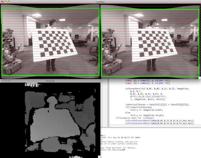
Parameters:
| cameraMatrix1 | First camera matrix. |
| distCoeffs1 | First camera distortion parameters. |
| cameraMatrix2 | Second camera matrix. |
| distCoeffs2 | Second camera distortion parameters. |
| imageSize | Size of the image used for stereo calibration. |
| R | Rotation matrix between the coordinate systems of the first and the second cameras. |
| T | Translation vector between coordinate systems of the cameras. |
| R1 | Output 3x3 rectification transform (rotation matrix) for the first camera. |
| R2 | Output 3x3 rectification transform (rotation matrix) for the second camera. |
| P1 | Output 3x4 projection matrix in the new (rectified) coordinate systems for the first camera. |
| P2 | Output 3x4 projection matrix in the new (rectified) coordinate systems for the second camera. |
| Q | Output \(4 \times 4\) disparity-to-depth mapping matrix (see reprojectImageTo3D ). |
| flags | Operation flags that may be zero or CALIB_ZERO_DISPARITY . If the flag is set, the function makes the principal points of each camera have the same pixel coordinates in the rectified views. And if the flag is not set, the function may still shift the images in the horizontal or vertical direction (depending on the orientation of epipolar lines) to maximize the useful image area. |
| alpha | Free scaling parameter. If it is -1 or absent, the function performs the default scaling. Otherwise, the parameter should be between 0 and 1. alpha=0 means that the rectified images are zoomed and shifted so that only valid pixels are visible (no black areas after rectification). alpha=1 means that the rectified image is decimated and shifted so that all the pixels from the original images from the cameras are retained in the rectified images (no source image pixels are lost). Obviously, any intermediate value yields an intermediate result between those two extreme cases. |
| newImageSize | New image resolution after rectification. The same size should be passed to initUndistortRectifyMap (see the stereo_calib.cpp sample in OpenCV samples directory). When (0,0) is passed (default), it is set to the original imageSize . Setting it to larger value can help you preserve details in the original image, especially when there is a big radial distortion. |
| validPixROI1 | Optional output rectangles inside the rectified images where all the pixels are valid. If alpha=0 , the ROIs cover the whole images. Otherwise, they are likely to be smaller (see the picture below). |
| validPixROI2 | Optional output rectangles inside the rectified images where all the pixels are valid. If alpha=0 , the ROIs cover the whole images. Otherwise, they are likely to be smaller (see the picture below). |
bool
cv::stereoRectifyUncalibrated(
    InputArray points1,
    InputArray points2,
    InputArray F,
    Size imgSize,
    OutputArray H1,
    OutputArray H2,
    double threshold = 5
    )
Computes a rectification transform for an uncalibrated stereo camera.
The function computes the rectification transformations without knowing intrinsic parameters of the cameras and their relative position in the space, which explains the suffix “uncalibrated”. Another related difference from stereoRectify is that the function outputs not the rectification transformations in the object (3D) space, but the planar perspective transformations encoded by the homography matrices H1 and H2 . The function implements the algorithm [37].
While the algorithm does not need to know the intrinsic parameters of the cameras, it heavily depends on the epipolar geometry. Therefore, if the camera lenses have a significant distortion, it would be better to correct it before computing the fundamental matrix and calling this function. For example, distortion coefficients can be estimated for each head of stereo camera separately by using calibrateCamera . Then, the images can be corrected using undistort , or just the point coordinates can be corrected with undistortPoints .
Parameters:
| points1 | Array of feature points in the first image. |
| points2 | The corresponding points in the second image. The same formats as in findFundamentalMat are supported. |
| F | Input fundamental matrix. It can be computed from the same set of point pairs using findFundamentalMat . |
| imgSize | Size of the image. |
| H1 | Output rectification homography matrix for the first image. |
| H2 | Output rectification homography matrix for the second image. |
| threshold | Optional threshold used to filter out the outliers. If the parameter is greater than zero, all the point pairs that do not comply with the epipolar geometry (that is, the points for which \(|\texttt{points2[i]}^T*\texttt{F}*\texttt{points1[i]}|>\texttt{threshold}\)) are rejected prior to computing the homographies. Otherwise,all the points are considered inliers. |
void
cv::triangulatePoints(
    InputArray projMatr1,
    InputArray projMatr2,
    InputArray projPoints1,
    InputArray projPoints2,
    OutputArray points4D
    )
Reconstructs points by triangulation.
The function reconstructs 3-dimensional points (in homogeneous coordinates) by using their observations with a stereo camera. Projections matrices can be obtained from stereoRectify.
Keep in mind that all input data should be of float type in order for this function to work.
Parameters:
| projMatr1 | 3x4 projection matrix of the first camera. |
| projMatr2 | 3x4 projection matrix of the second camera. |
| projPoints1 | 2xN array of feature points in the first image. In case of c++ version it can be also a vector of feature points or two-channel matrix of size 1xN or Nx1. |
| projPoints2 | 2xN array of corresponding points in the second image. In case of c++ version it can be also a vector of feature points or two-channel matrix of size 1xN or Nx1. |
| points4D | 4xN array of reconstructed points in homogeneous coordinates. |
See also:
void
cv::validateDisparity(
    InputOutputArray disparity,
    InputArray cost,
    int minDisparity,
    int numberOfDisparities,
    int disp12MaxDisp = 1
    )
validates disparity using the left-right check. The matrix “cost” should be computed by the stereo correspondence algorithm